Tuesday, 13 August 2013

Principle of DOL starter:

A Direct-On-Line (DOL) starter is an electronic 3-phase  control framework which offers delicate begins in DELTA conneection. DOL starters are presently replacing the utilization of manual or semi automatic "star-delta" starters. In the  beginning of a 3-Phase Induction motor, full line voltages are connected to the motor through contactors. The DOL is these days the most widely recognized sort of 3-Phase starter utilized.

It has an "closing circuit" and an "opening circuit". The closing circuit is for applying the supply lines to the motor and the opening -or "tripping" -circuit secures the motor by cutting-off (or "tripping") power to the motor from the administration lines if there is any over-load condition, single phasing fault etc.

DOL starting is sometimes used to start small  water pumps, compressor , fans and Conveyor belts. In the case of an asynchronous motor, such as the 3-phase, the motor will draw a high starting current until it has run up to full speed. This starting current is typically 6-7 times greater than the full load current. To reduce the inrush current, larger motors will have reduced-voltage starters or variablespeed drives in order to minimise voltage dips to the power supply.


 DOL starters are now and then used to start minor water pumps, compressor , fans and Conveyor cinchs For  induction motors, for example the 3-phase induction motor will draw a high beginning current until it has run up to full speed. This beginning current is regularly 6-7 times more stupendous than the full load current. To lessen the inrush current, bigger motors will have decreased voltage starters or variablespeed drives so as to minimise voltage dips to the force supply.

Connection Diagram of D.O.L starter:


Starters for Three Phase Induction Motors:
There are  many types of starters used for starting three phase induction motors depending upon size of motor and the work for which motor is used. Starter selection also depend upon construction of the motor. due to advancement in electronic control, electronic starters are also very famous now a days. process type and working conditions are also considered in starter selection.

There are basically two types of Induction Motors:
1.) Squirrel cage Induction Motor.
2.) Wound rotor Induction Motor.


1. Starters for Squirrel Cage Induction Motors:
  • Electromechanical starters.
  • Electronic starters.
2. Starters for wound rotor Induction Motor:
  • Rotor resistance starter.
Above two types can further be Classified as depicted in following diagram


Sunday, 11 August 2013


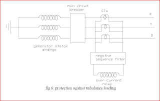
PROTECTION OF THE GENERATOR DUE TO UNBALANCE LOADING:

Because of fault there is an imbalance in the three phase stator currents and because of these irregularity flows, twofold frequency currents are impelled in the rotor center. This reasons the over warming of the rotor and therefore the rotor harm. Uneven stator currents likewise harm the stator. Negative sequence relay furnished with the over current relay is utilized for the assurance against unbalance stacking. From the hypothesis of the symmetrical parts, we realize that an unequal three phase currents hold the negative succession segment. This negative stage grouping current reasons warming of the stator. The negative warming takes after the safety law so it is corresponding to the square of the current. The warming time steady normally rely on the cooling framework utilized and is equivalent to I²t=k where I is the negative succession current and t is the present length of time in seconds and k is the steady normally lies between 3 and 20. Its general practice to utilize negative current transfers which matches with the above warming aspects of the generator. In this sort of insurance three Cts are joined with three stages and the yield from the secondaries of the Cts is bolstered to the loop of over current transfer through negative sequence relay. Negative sequence relay comprises of the resistors and capacitors and these are joined in such way that negative arrangement momentums courses through the hand-off curl. The transfer might be set to work at any specific quality of the unbalance ebbs and flows or the negative arrangement segment current

References:
1. Generator protection
http://www.cooperpower.com/Library/pdf/99066.pdf
2. Power system and protection
http://books.google.com/books?id=e0kdmbuWB0gC&pg=PA1&dq=generator+protectio
n&ei=I40fSLqaLKaiiwGIv_CKBg&sig=f8YRFoOQNFeheKHNB9u13v0ucSY#PPP1,M
1
3. Protective theory relaying and application by Walter A. Elmore
4. Voltage regulators
http://en.wikipedia.org/wiki/Voltage_regulator
5 power engineering
http://en.wikipedia.org/wiki/Power_engineering
6. Google books of power system stability and control by Leonard L. Grigsby

Saturday, 10 August 2013


 Over voltage Protection:

 Over voltage happens in light of the increment in the speed of the prime mover because of sudden loss in the burden on the generator. Generator over voltage does not happen in the turbo generator in light of the fact that the control governors of the turbo generators are extremely touchy to the speed variety. Anyway the over voltage insurance is needed for the hydro generator or gas turbine generators. The over voltage assurance is furnished by two over voltage transfers have two units – one is the immediate transfers which is situated to get at 130 to 150% of the evaluated voltage and an alternate unit is IDMT which is situated to get at 110% of evaluated voltage. Over voltage might happen because of the inadequate voltage controller and additionally because of manual control errors

Under voltage security:

If more than one generators supply the burden and because of some excuse for why one generator is abruptly outing , then an alternate generators attempt to supply the load. Each of these generators will experience a sudden build in current and subsequently diminishes the terminal voltage. Immediate voltage controller joined with the framework attempt to restore the voltage. What's more under voltage relay type-27 is likewise utilized for the under voltage insurance.


UNDER/OVER FREQUENCY PROTECTION:

Over frequency results from the excess generation and it can easily be corrected by reduction in the power outputs with the help of the governor or manual control.

 Under frequency operation: Under frequency occurs due to the excess. During an overload, generation capability of the generator increases and reduction in frequency occurs. The power system survives only if we drop the load so that the generator output becomes equal or greater than the connected load. If the load increases the generation, then frequency will drop and load need to shed down to create the balance between the generator and the connected load. The rate at which frequency drops depend on the time,
amount of overload and also on the load and generator variations as the frequency changes. Frequency decay occurs within the seconds so we can not correct it manually. Therefore automatic load shedding facility needs to be applied.

These schemes drops load in steps as the frequency decays. Generally load shedding drops 20 to 50% of load in four to six frequency steps. Load shedding scheme works by tripping the substation feeders to decrease the system load. Generally automatic load shedding schemes are designed to maintain the balance between the load connected and the generator. The present practice is to use the under frequency relays at various load points so as to drop the load in steps until the declined frequency return to normal. Non
essential load is removed first when decline in frequency occurs. The setting of the under frequency relays based on the most probable condition occurs and also depend upon the worst case possibilities.
During the overload conditions, load shedding must occur before the operation of the under frequency relays. In other words load must be shed before the generators are tripped.

 Generation of sinusoidal voltage:


 There are two facts that the voltage developed in a coil of a generator changes; the first one is it changes in magnitude from instant to instant as varying values of flux are cut per second and the other one is it changes in direction as coil side change positions under north and south poles, implies that alternating emf is generated. This means that the voltage is maximum as mentioned in our last topic here when the position of the coil is just like shown in the figure below

and will diminish to zero as the coil rotates clockwise toward the position as shown below: - See more at: http://electricalengineeringforbeginners.blogspot.in/#sthash.KN4iRb1Q.dpuf and will diminish to zero as the coil rotates clockwise toward the position as shown


and will diminish to zero as the coil rotates clockwise toward the position as shown


Then, as the coil continues to rotate clockwise, the polarities will change. Assuming uniform flux distribution between north and south poles, the generated voltage in a coil located from the vertical will be


Then, as the coil continues to rotate clockwise, the polarities will change. Assuming uniform flux distribution between north and south poles, the generated voltage in a coil located from the vertical will be: - See more at: http://electricalengineeringforbeginners.blogspot.in/#sthash.KN4iRb1Q.dpuf


Then, as the coil continues to rotate clockwise, the polarities will change. Assuming uniform flux distribution between north and south poles, the generated voltage in a coil located from the vertical will be:
- See more at: http://electricalengineeringforbeginners.blogspot.in/#sthash.KN4iRb1Q.dpuf

Subscribe to RSS Feed Follow me on Twitter!